
Repeatable inspection routes
Plan an observation mission around asset rows or selected checkpoints and retain a record of completed coverage.
03 / Aerial inspection & surveillance
A wider view. A complete mission.
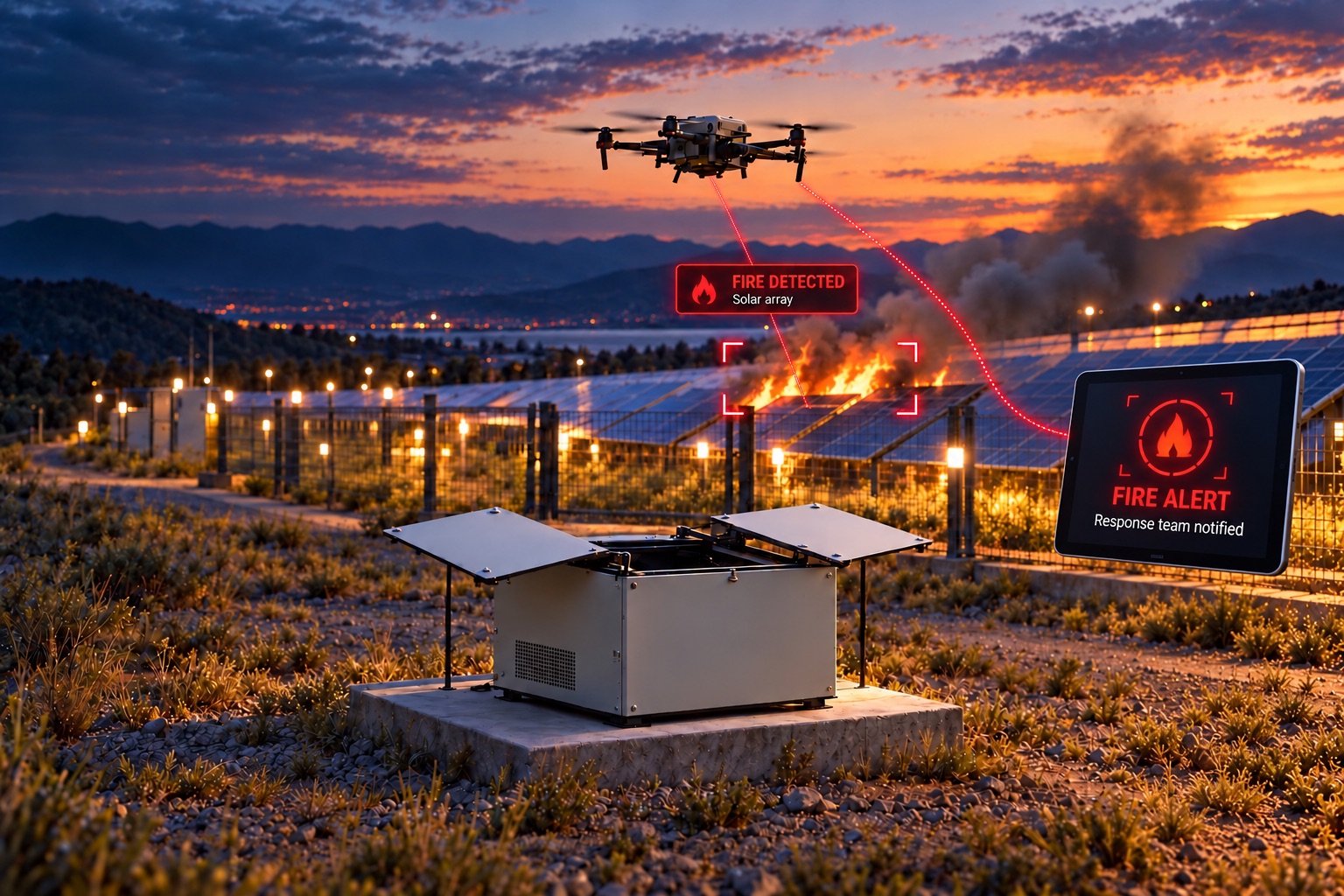
An aerial observation concept that brings the aircraft, mission software and ground dock into one workflow. Plan a site inspection, capture useful evidence and return for a verified landing and recharge.
Technical reference · Version 1.0 · 1 November 2026
01 / THE PURPOSE
Aerial inspection can connect observations across large or hard-to-reach assets. A drone-in-a-box concept adds a ground dock and repeatable mission workflow to the aircraft. The difficult part is the complete operating cycle: readiness, permitted flight, useful sensing, return, landing confirmation and energy recovery. Each transition needs observable state and a defined failure response.
Plan an observation mission around asset rows or selected checkpoints and retain a record of completed coverage.
Associate images with mission time and position. Select an RGB, thermal or other payload only when its task and integration are defined.
Treat the dock, return procedure, landing confirmation and charging checks as part of the system design.
Observe panel rows and send candidate anomalies for specialist review.
Gather elevated views of agreed assets and boundaries within a permitted operating area.
Repeat asset-focused missions with a payload and flight profile selected for the inspection task.
02 / FROM PLAN TO ACTION
Select a step or play the sequence. Change the scenario to explore a different outcome. This is an explanatory simulation, not a connected device.
Normal mission · Readiness checks assumed satisfied.
STEP 01 / 06
An operator defines the permitted flight area, route, payload task, return location and response policy. A scheduled time alone is not permission to launch.
A candidate event requires operator review. Mission success and alert acknowledgement are separate outcomes.
03 / SYSTEM ARCHITECTURE
Separate sensing, mission logic, local control and operator review. The diagram is a proposed allocation of responsibilities; component selection and interfaces are agreed during engineering.
Collect inspection imagery and associated capture metadata. Payload selection determines what can be meaningfully observed.
Plan permitted tasks, process observations and exchange mission state with the operator. This is separate from the flight-control loop.
A selected flight stack manages stabilization and configured responses to faults. Vehicle and software configuration determine supported behaviors.
Verify readiness, landing and charge state. The dock needs its own health checks, interlocks and maintenance plan.
Motion or flight responses must have a defined local policy. A web dashboard, cloud connection or language model is not a substitute for the platform's assessed control and stop / recovery systems.
In a candidate PX4-based architecture, the flight controller and companion computer have distinct jobs. The flight controller handles flight; the companion supports mission and observation logic. Higher-level software should not bypass configured aircraft limits.
A protocol such as MAVLink can exchange mission plans with an aircraft. Uploaded, accepted, active, interrupted and completed are different states. The operator needs confirmation of execution and recorded coverage, not only an upload result.
Returning near a dock, landing on it and establishing charge are separate outcomes. Define how alignment, contact, charging and enclosure status are verified. A failed landing or charging check should keep the system out of the ready state.
Technology background: PX4: system architecture · PX4: failsafe configuration · MAVLink: mission protocol. These sources explain components, not Xcugas product certification or integration status.
04 / HARDWARE & CONFIGURATION
Each layer has a job and an acceptance question. The final bill of materials, operating envelope and test evidence belong to the agreed project configuration.
| Subsystem | Candidate configuration | What to verify |
|---|---|---|
| Aircraft | Airframe, motors, propulsion and flight controller | Payload mass, balance, vibration, controllability and energy consumption. |
| Navigation sensing | Selected position, inertial and height sensors | Position quality and behavior when individual inputs degrade. |
| Inspection payload | RGB, thermal or other scoped sensor | Resolution at the working distance, calibration, capture conditions and mounting. |
| Companion compute | Optional mission / perception processor | Interface compatibility, processing load, heat and power consumption. |
| Dock | Landing interface, charging and enclosure systems | Alignment, contacts, environmental protection, interlocks and status feedback. |
| Communications | Telemetry and evidence links | Coverage, bandwidth, authorization and tested link-loss behavior. |
No fixed speed, runtime, range, payload, ingress rating or accuracy figure is asserted in this reference design. Request a configuration-specific specification and supporting test results.
05 / SOFTWARE & DATA
A useful integration preserves data meaning: where the observation happened, when it was captured, which mission it belongs to and whether an operator has reviewed it.
| Interface | Information exchanged | Integration requirement |
|---|---|---|
| Operator → mission system | Route, inspection task and permitted area | Validate the mission before upload and record configuration revision. |
| Mission system → flight controller | Mission exchange / telemetry through a selected interface | Track acceptance, execution state and interruption; supported commands are project-specific. |
| Payload → evidence service | Images and capture metadata | Preserve timestamps, sensor settings and location quality. |
| Dock → operations | Landing, enclosure, charge and fault states | Require positive confirmation before advertising readiness for the next launch. |
Retries should preserve the event identifier to avoid duplicate cases. A server receipt does not mean a human has acknowledged the event. Offline observations retain their original capture time.
ILLUSTRATIVE EVENT CONTRACT
{
  "event_id": "drone-example-001",
  "mission_id": "patrol-example",
  "platform": "drone",
  "captured_at": "2026-11-01T10:00:00Z",
  "location": {
    "frame": "site_map",
    "checkpoint": "review-zone"
  },
  "type": "observation_for_review",
  "evidence_ref": "access-controlled-reference",
  "delivery_state": "queued",
  "review_state": "unreviewed"
}
Example fields only. This is not a published API or live event.
Define operator roles, device identity and authenticated connections. Privileged commands need an audit trail and a clear authority model.
Agree which evidence is collected, who can see it and how long it is retained. Use restricted capture zones and masking where the site requires them.
Mark stale telemetry visibly. Test reconnection, event de-duplication and expired-command rejection. Do not expose robot control interfaces directly to the public internet.
06 / OPERATING BOUNDARIES
Normal operation is only part of the design. Agree what happens when the environment, position estimate, energy or communications no longer support the mission.
| Condition | Proposed response | Acceptance evidence |
|---|---|---|
| Readiness check fails | Inhibit launch and expose the failed condition to the operator. | A schedule cannot override aircraft, dock or environmental readiness. |
| Energy reaches reserve | Interrupt inspection and execute the validated return or landing policy. | Incomplete coverage is recorded; reserve is verified for the actual payload and conditions. |
| Ground link is lost | Apply the configured onboard flight response and buffer available evidence. | The selected response is tested; the ground view is marked stale. |
| Landing or charge is unconfirmed | Keep the system unavailable for a new launch and request intervention. | Return-to-home, landing and charging are measured as separate outcomes. |
Flight permissions and local operating constraints must be established for the installation. This document does not establish regulatory authorization.
Wind, precipitation, visibility, temperature and electromagnetic conditions need explicit limits and a no-launch policy.
A thermal or visual pattern alone does not prove a fire or equipment fault. Sensor calibration and specialist review may be required.
Flight endurance, range, payload, wind rating, inspection accuracy and autonomous-docking success are not claimed here.
07 / COMMISSIONING & VALIDATION
Set acceptance thresholds before the pilot. Measure the agreed configuration under representative conditions and document the cases where it needs help.
Document the task, operating area, environment, users and intervention responsibilities.
Select the hardware and software, calibrate sensors and define interfaces and exception policies.
Test normal missions, false events, interruptions and recovery. Retain logs and operator observations.
Sign off measured results, train operators and schedule checks. Revalidate after material changes.
| Measure | How to evaluate it | Test conditions |
|---|---|---|
| Launch readiness | Correctly inhibited / permitted test launches | Exercise failed sensors, unavailable dock and out-of-envelope conditions. |
| Inspection coverage | Usable captured checkpoints / planned checkpoints | Report image quality and interrupted missions. |
| Evidence quality | Reviewable observations against a labelled reference set | Account for height, angle, lighting and selected payload. |
| Recovery behavior | Observed response to link, energy and position faults | Test the chosen policy in controlled conditions before site use. |
| Docking cycle | Return, landing and verified charge success rates separately | Log each transition; do not count arrival near the dock as success. |
For each measure, record the target, sample size, conditions, software version, hardware configuration and result. Targets are agreed with the customer; this document contains no benchmark results or promised performance levels.
Provide asset layouts, proposed inspection tasks, operating permissions, site constraints, payload needs, communications coverage, environmental limits and a dock location. Nominate the flight-operations owner and the team that reviews evidence.
08 / TECHNICAL WHITE PAPER
Download the complete reference: purpose, mission flow, architecture, interfaces, operating boundaries, test plan and sources.
The architecture is a proposed engineering design, informed by the existing Xcugas platform descriptions and the technical sources below. External documentation describes component behavior; it does not establish a deployed integration or a performance guarantee.
Describes flight-controller and companion-computer responsibilities.
Describes configurable responses to battery, position and connection faults.
Describes exchanging mission, geofence and safe-point plans with an aircraft.
Source review: 1 November 2026. Links may describe evolving software; pin and validate versions during implementation.
A LITTLE MORE CLARITY
No. A dock and an automated workflow do not establish permission or suitability for unattended operation. The operating model must be assessed for the site.
This design routes candidate observations for review. It does not claim certified fire detection or a diagnostic accuracy figure.
No. Return, landing, contact and verified charging are separate states, each requiring its own confirmation and failure handling.
Start something extraordinary
Tell us what you want to make possible. Let's find the right hardware, connectivity and path forward.
hello@xcugas.comOTHER SURVEILLANCE PLATFORMS