
Repeatable rounds
Visit agreed checkpoints and record missed locations rather than treating an incomplete route as a successful patrol.
01 / Indoor surveillance
Every route. A clearer picture.
A mobile observation platform for mapped indoor spaces. Connect a robot chassis, site-aware navigation and an operator workflow to turn patrol rounds into reviewable evidence.
Technical reference · Version 1.0 · 1 November 2026
01 / THE PURPOSE
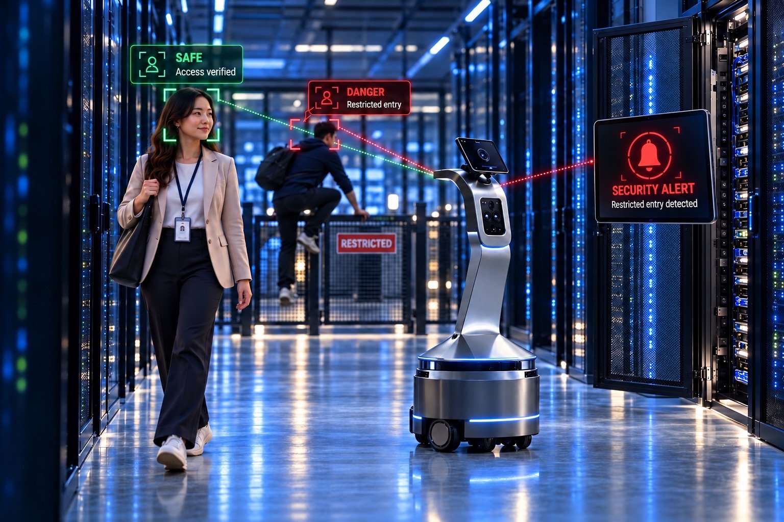
Fixed cameras provide a consistent view of selected locations. A mobile robot adds a changing viewpoint along a planned route. This reference design focuses on repeatable indoor inspection, recording where an observation occurred and routing it to an operator. It does not determine a person's identity or grant access to a controlled area.
Visit agreed checkpoints and record missed locations rather than treating an incomplete route as a successful patrol.
Pair an observation with the mission, map location and capture time so a team can decide what to do next.
Choose the body, cameras and application workflow around the site, using the chassis and software interfaces as a foundation.
Observe agreed equipment-room approaches and route potential restricted-zone events for review.
Check accessible corridors, doors and selected assets during scheduled rounds.
Repeat patrols through mapped, controlled spaces where pedestrian interaction can be assessed.
02 / FROM PLAN TO ACTION
Select a step or play the sequence. Change the scenario to explore a different outcome. This is an explanatory simulation, not a connected device.
Normal mission · Readiness checks assumed satisfied.
STEP 01 / 06
An operator selects the approved map, checkpoints and observation rules. The mission receives an identifier so every later event can be traced to its route.
A candidate event requires operator review. Mission success and alert acknowledgement are separate outcomes.
03 / SYSTEM ARCHITECTURE
Separate sensing, mission logic, local control and operator review. The diagram is a proposed allocation of responsibilities; component selection and interfaces are agreed during engineering.
Time-stamped measurements describe nearby geometry, visual context and motion. Sensor placement and calibration must be verified on the assembled robot.
Maintain a map-relative pose and calculate an allowed path. A local controller translates the path into bounded motion requests.
Motor feedback closes the motion loop. A separately assessed stop path must remain available without a cloud connection.
Observations become reviewable events. Operators receive health, mission state and evidence links through authenticated interfaces.
Motion or flight responses must have a defined local policy. A web dashboard, cloud connection or language model is not a substitute for the platform's assessed control and stop / recovery systems.
SLAM builds or updates a map while estimating motion. A routine patrol may instead localize against an approved map. Door changes, moved equipment and reflective surfaces can reduce confidence; commissioning must define when to stop and relocalize.
A candidate ROS 2/Nav2 integration separates route planning from the controller that follows it. Define the robot footprint, clearance and permitted zones using the actual body and payload. A camera-based alert should not override motion constraints.
An event rule should consider zone, time and repeated observations. Keep evidence and operator decisions together. Tune thresholds against representative lighting and traffic, and record both false alerts and missed examples.
Technology background: Nav2: navigation servers · ROS 2: quality of service. These sources explain components, not Xcugas product certification or integration status.
04 / HARDWARE & CONFIGURATION
Each layer has a job and an acceptance question. The final bill of materials, operating envelope and test evidence belong to the agreed project configuration.
| Subsystem | Candidate configuration | What to verify |
|---|---|---|
| Mobile base | Drive motors, encoders and chassis | Footprint, turning space, floor transitions, braking and payload stability. |
| Range sensing | 2D LiDAR and optional depth sensing | Coverage near glass, dark surfaces, overhangs and low obstacles. |
| Observation | RGB camera; other payloads by scope | Field of view, low-light quality, privacy masks and camera placement. |
| Compute & control | Onboard computer and drive controller | Processing load, thermal limits, watchdogs and sensor time alignment. |
| Power & docking | Battery management and charging interface | Usable mission energy, reserve policy, contact alignment and charging verification. |
| Connectivity | Site Wi-Fi or scoped network link | Coverage gaps, roaming behavior, buffering and reconnection handling. |
No fixed speed, runtime, range, payload, ingress rating or accuracy figure is asserted in this reference design. Request a configuration-specific specification and supporting test results.
05 / SOFTWARE & DATA
A useful integration preserves data meaning: where the observation happened, when it was captured, which mission it belongs to and whether an operator has reviewed it.
| Interface | Information exchanged | Integration requirement |
|---|---|---|
| Sensor → autonomy | Time-stamped scans, images and odometry | Define frames, units, update expectations and stale-data behavior. |
| Mission → motion | Approved waypoints and navigation goals | Require preconditions, cancellation handling and state feedback. |
| Robot → dashboard | Health, mission state and observations | Include capture time, receive time and a visible freshness indicator. |
| Dashboard → robot | Authorized mission / pause / resume requests | Validate ownership, expiry and acknowledgement before changing state. |
Retries should preserve the event identifier to avoid duplicate cases. A server receipt does not mean a human has acknowledged the event. Offline observations retain their original capture time.
ILLUSTRATIVE EVENT CONTRACT
{
  "event_id": "robot-example-001",
  "mission_id": "patrol-example",
  "platform": "robot",
  "captured_at": "2026-11-01T10:00:00Z",
  "location": {
    "frame": "site_map",
    "checkpoint": "review-zone"
  },
  "type": "observation_for_review",
  "evidence_ref": "access-controlled-reference",
  "delivery_state": "queued",
  "review_state": "unreviewed"
}
Example fields only. This is not a published API or live event.
Define operator roles, device identity and authenticated connections. Privileged commands need an audit trail and a clear authority model.
Agree which evidence is collected, who can see it and how long it is retained. Use restricted capture zones and masking where the site requires them.
Mark stale telemetry visibly. Test reconnection, event de-duplication and expired-command rejection. Do not expose robot control interfaces directly to the public internet.
06 / OPERATING BOUNDARIES
Normal operation is only part of the design. Agree what happens when the environment, position estimate, energy or communications no longer support the mission.
| Condition | Proposed response | Acceptance evidence |
|---|---|---|
| Obstacle blocks the route | Stop, attempt only an allowed replan, then pause for assistance. | No contact; an interrupted mission remains visibly incomplete. |
| Position confidence drops | Suspend motion and require a validated recovery or operator intervention. | The robot does not continue along a pose estimate known to be unreliable. |
| Network connection drops | Apply the configured local pause policy and buffer events with original timestamps. | Dashboard shows stale data; queued and delivered events remain distinct. |
| Energy reaches reserve | End the patrol and attempt the validated return procedure if feasible. | Reserve is tested under the configured load; charging is confirmed separately. |
A map is not a guarantee that a corridor remains clear. Reassess routes after layout changes.
Stairs, lifts and automatic doors require separate integration and validation; do not assume they are supported.
Pedestrian behavior, visibility and stopping distance must be evaluated for the specific installation.
Runtime, speed, payload, dimensions, detection accuracy and charging time remain configuration-specific.
07 / COMMISSIONING & VALIDATION
Set acceptance thresholds before the pilot. Measure the agreed configuration under representative conditions and document the cases where it needs help.
Document the task, operating area, environment, users and intervention responsibilities.
Select the hardware and software, calibrate sensors and define interfaces and exception policies.
Test normal missions, false events, interruptions and recovery. Retain logs and operator observations.
Sign off measured results, train operators and schedule checks. Revalidate after material changes.
| Measure | How to evaluate it | Test conditions |
|---|---|---|
| Route completion | Completed checkpoints / scheduled checkpoints | Include blocked and interrupted runs in the report. |
| Obstacle response | Stop clearance and intervention count | Test representative people, objects and floor conditions. |
| Observation quality | Precision and recall on a labelled test set | Include day/night scenes and difficult negative examples. |
| Alert lifecycle | Capture-to-receipt and receipt-to-acknowledgement time | Report tail latency and connectivity failures, not just averages. |
| Return & charge | Successful docking and verified charge sessions / attempts | Include low-energy and alignment-error cases. |
For each measure, record the target, sample size, conditions, software version, hardware configuration and result. Targets are agreed with the customer; this document contains no benchmark results or promised performance levels.
Provide floor plans, permitted routes, clearance constraints, observation examples, privacy zones, network coverage and a charging location. Define who reviews events and who can recover a paused robot.
08 / TECHNICAL WHITE PAPER
Download the complete reference: purpose, mission flow, architecture, interfaces, operating boundaries, test plan and sources.
The architecture is a proposed engineering design, informed by the existing Xcugas platform descriptions and the technical sources below. External documentation describes component behavior; it does not establish a deployed integration or a performance guarantee.
Explains the separation of planning, control and recovery in a ROS-based navigation system.
Describes message delivery policies and publisher/subscriber compatibility.
Source review: 1 November 2026. Links may describe evolving software; pin and validate versions during implementation.
A LITTLE MORE CLARITY
This design supports observation and operator review. Response, escalation and access decisions stay with the designated team.
ROS 2 and Nav2 are candidate components in this reference architecture. The delivered stack, supported versions and interfaces must be confirmed in the project scope.
Local behavior must be defined and tested. The illustrated policy pauses the patrol and buffers events; it does not promise uninterrupted remote monitoring.
Start something extraordinary
Tell us what you want to make possible. Let's find the right hardware, connectivity and path forward.
hello@xcugas.comOTHER SURVEILLANCE PLATFORMS